| Jerusalem |
| The Western Wall Tunnels, The Hasmonean Aqueduct |
| Conservation Measures for Removing Hazards |
| Orderer | Western Wall Heritage Foundation |
| Duration | October 2007 - July 2009 |
| Implemented by: |
Evgeny Ivanovsky
Aliza Van Zaiden
Shiran Sabag
Amit Rosenblum
'Attoun Hader
Yossi Vaknin
Eetai Abksis
Ariel Yogev
Hader Shchada
Tsagai Asma'in
Arch. Marcus Edelcopp
|
In 2006 an engineering survey was conducted in the Hasmonean aqueduct as part of the conservation measures carried out in the Western Wall tunnels on behalf of the Western Wall Heritage Foundation. The survey, which was performed by conservation engineer Ofer Cohen, defined the constructive and physical conditions of the aqueduct. The principal factors the survey identified as affecting the aqueduct’s state of preservation are the load exerted by the buildings that were constructed above the aqueduct and the seepage of rainwater.
In the wake of the survey findings the Western Wall Heritage Foundation requested that the Israel Antiquities Authority implement the necessary measures for conserving the aqueduct in order to allow the public to safely enter the site. The conservation steps were taken so as to stabilize the structural components of the aqueduct.
Description of the Aqueduct
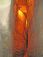
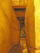
The aqueduct conveyed water from the vicinity of Hebron to that of the Temple Mount. The northern section of the aqueduct, where the conservation intervention was carried out, is a deep channel that is hewn in the bedrock. It is approximately 90 meters long, 0.5-0.9 meters wide and varies in height from 1.90 meters in the south to 5 meters high in the north. It is widely believed that this section was hewn in the Hasmonean period. The channel was covered with stone slabs, probably during the Middle Ages, in order to keep it clean. A maximum of four courses of medium size stones (c. 0.3 x 0.5 m) were built with the aim of straightening the surface level and facilitating the placement of the stone covering slabs. Its tall narrow dimensions, the hewn bedrock and obvious signs of water erosion render the place a special atmosphere. The aqueduct functioned as a water conduit until the Ottoman period. In the 1970’s the aqueduct was dried out and prepared so that the public could walk through it.
The Conservation Measures
Documentation. The aqueduct was documented for the purpose of conservation planning and this included gathering up-to-date information regarding its state of preservation. This information served as a basis for planning the intervention. The documentation also included measuring the aqueduct, drawing plans of its current state, testing its environmental, humidity and salinity conditions, testing the strength of the covering stones, recording cracks, checking the kinds of stone and photographing the existing state of the aqueduct.
Examining the State of Preservation. A number of tests were done to identify conservation problems:
• Test Drillings:
o Test drillings were done in the covering stones: the test shows the physical condition of the stone. A visual examination revealed that the surface of the stone is peeling and crumbling. The aim of the test drillings was to check the depth of the deterioration.
o Test drillings through the covering stones in order to examine what is situated above these stones. This test revealed cavities, which are filled with soil and small stones, and drainage channels from later periods.
• Superimposing Survey Plans: this test makes it possible to analyze and understand the built-up spaces above the aqueduct’s stone covering. Using Charles Warren’s plan (from 1867-1870) and that of Reuven Alstar (November 2007), we are able to estimate the loads that are being exerted on the covering stones, as well as the volume of fill that is above them.
We concluded from the test findings that there are different conditions above the course of the aqueduct that affect the state of its preservation: buildings were erected on both sides of the aqueduct and their loads bear down on the sides of the conduit and on its ceiling; a wall that was built on it is exerting an excessive load on the covering stones and causing damage; a leaky drainage channel that runs along the route of the aqueduct caused seepage and washed away the fill from above and alongside the covering stones. In addition to this the leaking water caused micro-organisms to spread over the surface of the stones and bedrock.
• Checking the Cavities by means of a Burrow-scope. Following the collapse of some of the covering stones it was decided to check the condition of the material above them. This test allowed us to determine the state of the stone: stable stone, fractured stone or collapsed stone.
The test drillings and the burrow-scope examination revealed three different conditions that are present above the covering stones:
1. A layer of stable fill that probably dates to the Middle Ages.
2. A layer of unstable soil and small stones.
3. Cavities that were formed as a result of seeping water and fill that was washed away.
• Microbiological Tests. Samples of the microbiological flora (lichen, fungi) were taken for laboratory analysis. Dr. Natalya Roknin identified the kinds of micro-organisms that are growing there and methods for treating them were determined. The test revealed that there are bacterial foundations, red and green algae and a number of species of fungi that are present in the aqueduct.
The Main Problems that were Identified in the Aqueduct:
1. Crevices in the bedrock, in the bottom of the aqueduct, as a result of the decomposition that stems from the structure of the rock and the seasonal flow of water.
2. Cracking in the bedrock.
3. Missing covering stones.
4. Collapsed covering stones.
5. Cracked covering stones.
6. Deterioration of the stone and mortar in the built parts of the aqueduct.
7. Cavities behind the building stones as a result of the fill having been washed away.
8. Collapsed covering stones and stone fill at the northern end of the aqueduct.
9. The use of cement in conservation measures that were implemented in the 1970s.
The test findings were useful in understanding the processes that caused the deterioration and destruction of the aqueduct, and together with the conservation principles, allowed us to make informed decisions regarding its treatment.
Intervention Principles
In order to preserve the value of the site and the authenticity of the aqueduct we had to minimize the damage to the bedrock and select methods of intervention that are as discreet as possible.
The main principles of intervention in the aqueduct are:
• Respecting the original fabric.
• Minimal intervention.
• Retreatability.
Conservation Measures
1. Covering Stones
Two basic solutions were used to strengthen the covering stones; each stone was reinforced according to its state of preservation:
1a. Stabilizing by means of a stainless steel profile. In places where there were deep fissures, deformation and the danger of collapse. This solution does not damage the covering stones but is liable to harm the bedrock. Although visually conspicuous, the disturbance can be minimized by placing the profiles at the edge of the supported stone and implementing this solution in only certain sections rather than along the entire length of the aqueduct.
2a. Stabilizing by means of stainless steel pins. This solution was implemented in those places where the crack in the stone was superficial and there was no apparent danger of collapse or falling. This solution is relatively simple to do and it can be concealed. The disadvantage of it is that it requires inserting a foreign body into the stone and damaging it.
Another solution that was proposed was using anchors to stabilize the covering stones. This solution was rejected because of the structural damage that it causes to the stone, the aesthetic damage and the expensive cost of implementing it. It was also determined that drilling the holes for the anchors was likely to cause damage to the buildings that are situated above the aqueduct.
It was not possible to implement these solutions for stabilizing the covering in the northern part of the channel and therefore the following solutions were applied there:
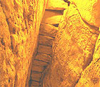
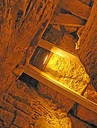
3a. Using railroad ties to fill the place of missing covering stones. In those places where covering stones were missing as a result of having been broken or there is no proof they ever existed, the aqueduct was covered by means of railroad ties. Tar was applied to the upper surface of the ties in order to inhibit wood decay. Mortar was injected into the cavities above the ties and in those places that were accessible, mortar and tuff (5-8 cm) fill was deposited so as to minimize the weight on the railroad ties. The opening through which the fill was inserted was sealed with debesh construction. The disadvantage of this form of intervention is that the railroad ties require constant maintenance.
4a. Artificial construction. The bedrock on the western side of the aqueduct is cracked and friable. The solution was to quarry along the top of the deteriorating bedrock to a depth of c. 30 centimeters and a height of c. 20-25 centimeters, and fill in the missing rock with mortar. Stainless steel pins were inserted in order to reinforce this construction.
5a. Installing steel profiles. More massive intervention was necessary in the region where the channel becomes wider and the bedrock is cracked and friable. In the first phase the covering stones were stabilized with a lime-based mortar and holes were drilled in order to install the profiles. The drilling on the western side was done in a fan-like fashion that would facilitate installing the profile from the bottom up. The holes on the eastern side were drilled to a depth of c. 50 centimeters so as to make it possible to insert the profile into the opposite side. In the second phase, the railroad ties were leaned against the western wall of the channel and were temporarily supported on top of screw jacks. Finally when the placement of the profiles was completed the cement material was removed and new lime-based mortar was applied.
6a. “Upside down steps”. At the northern end of the aqueduct there is a concentration of collapsed covering stones and fill that was reinforced with mesh in the 1970s; “upside down steps” were built of railroad ties in order to prevent further collapse. The space above the railroad ties was filled with debesh construction or tuff and mortar.
2. Stone Completions and Repairs to the Bedrock
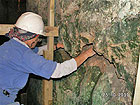
The crevices in the bedrock and the regions that were in danger of collapse, which extended over a relatively small area, were filled in with mortar. Wide crevices in the bedrock were also filled in with mortar, but these were reinforced utilizing stainless steel rods that are 8 and 10 millimeters in diameter. In sections where the deterioration was advanced, where the surface of the rock was cracked and crumbling, the rock was cleaned of loose pieces of stone to a depth of 20-25 centimeters and the resulting cavity was then filled with debesh construction.
3. Completing Missing Stonework
In those places where the covering stones were located on ancient construction, the construction was reinforced with mortar and the missing stonework was completed with stones in secondary use that were found at the site or with stones that match the original stone.
4. Mortar
4a. Pointing up the joints with mortar. This step was implemented utilizing mortar composed of pit-lime, hydraulic lime, quarry sand, gravel, ceramics and ash.
4b. Mortar injection (grouting). This measure was taken in order to fill the spaces between the top of the bedrock and the covering stones and above the railroad ties. The mortar is composed of pit lime, hydraulic lime, powdered ash, powdered stone and powdered ceramic.
5. Stainless steel Reinforcements
Stainless steel pins (Carbon 316) with a matte finish were utilized at the site due to the high level of humidity in the aqueduct and the seeping water. Various diameter rods were used to reinforce the covering stones that were not deformed and in sections of bedrock that were disintegrating. Approximately 30 per cent of the covering stones in the aqueduct were set on stainless steel profiles (IPN 100). White cement was applied to the ends of the profiles in order to protect the profile from the effects of the lime in the mortar. The gap between the profile and the covering stone was filled with white cement. A layer of nylon was installed in order to protect the stone from the effects of the cement. The nylon is not likely to decompose since it is not exposed to air or sunlight. Steel profiles were installed to support the covering stones at the northern end of the aqueduct where the channel winds.
It should be mentioned that the microbiological organisms were not treated because of budgetary considerations.
By the time the conservation measures were completed in July 2009 all of the hazards had been removed from the aqueduct.
-------------------------------
Evgeny Ivanovsky and Amit Rozenblum
January 2010
To view the figures, click on the figure caption
|
|